
The Epicyclic Gear Train Is Driven by the Rotating Link De

This planetary gear railroad train consists of a sun gear (yellow), planet gears (bluish) supported by the carrier (green) and a band gear (pinkish). The red marks show the relative displacement of the sun gear and carrier, when the carrier is rotated 45° clockwise and the ring gear is held fixed.
An epicyclic gear train (as well known as a planetary gearset) consists of two gears mounted and then that the center of ane gear revolves around the heart of the other. A carrier connects the centers of the two gears and rotates the planet and sun gears mesh so that their pitch circles roll without slip. A point on the pitch circumvolve of the planet gear traces an epicycloid curve. In this simplified example, the sunday gear is fixed and the planetary gear(due south) roll effectually the sun gear.
An epicyclic gear railroad train can be assembled so the planet gear rolls on the within of the pitch circle of a fixed, outer gear ring, or band gear, sometimes called an annular gear. In this case, the curve traced by a point on the pitch circle of the planet is a hypocycloid.
The combination of epicycle gear trains with a planet engaging both a lord's day gear and a band gear is called a planetary gear train.[1] [2] In this example, the ring gear is usually fixed and the dominicus gear is driven.
Overview [edit]
Epicyclic gearing or planetary gearing is a gear system consisting of one or more outer, or planet, gears or pinions, revolving near a central sun gear or lord's day wheel.[3] [4] Typically, the planet gears are mounted on a movable arm or carrier, which itself may rotate relative to the sunday gear. Epicyclic gearing systems too contain the use of an outer ring gear or annulus, which meshes with the planet gears. Planetary gears (or epicyclic gears) are typically classified equally uncomplicated or compound planetary gears. Uncomplicated planetary gears accept 1 sun, one ring, one carrier, and one planet set. Compound planetary gears involve one or more of the following three types of structures: meshed-planet (at that place are at least ii more planets in mesh with each other in each planet train), stepped-planet (there exists a shaft connectedness betwixt two planets in each planet train), and multi-stage structures (the organisation contains ii or more planet sets). Compared to uncomplicated planetary gears, compound planetary gears take the advantages of larger reduction ratio, higher torque-to-weight ratio, and more flexible configurations.
The axes of all gears are usually parallel, but for special cases like pencil sharpeners and differentials, they tin be placed at an angle, introducing elements of bevel gear (see below). Further, the lord's day, planet carrier and ring axes are usually coaxial.
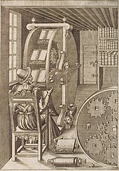
Bookwheel, from Agostino Ramelli'due south Le diverse et artifiose machine, 1588
Epicyclic gearing is besides available which consists of a sun, a carrier, and two planets which mesh with each other. 1 planet meshes with the dominicus gear, while the 2d planet meshes with the ring gear. For this case, when the carrier is fixed, the ring gear rotates in the same direction as the sunday gear, thus providing a reversal in direction compared to standard epicyclic gearing.
History [edit]
At around 500 BC, the Greeks invented the thought of epicycles, of circles travelling on the round orbits. With this theory Claudius Ptolemy in the Almagest in 148 Advertising was able to predict planetary orbital paths. The Antikythera Mechanism, circa lxxx BC, had gearing which was able to approximate the moon's elliptical path through the heavens, and even to right for the nine-twelvemonth precession of that path.[five] (The Greeks would accept seen it not as elliptical, merely rather as epicyclic motility.)
In the 2nd-century Advert treatise Almagest, Ptolemy used rotating deferent and epicycles that form epicyclic gear trains to predict the motions of the planets. Accurate predictions of the motility of the Sun, Moon and the five planets, Mercury, Venus, Mars, Jupiter and Saturn, across the sky assumed that each followed a trajectory traced past a bespeak on the planet gear of an epicyclic gear train. This bend is called an epitrochoid.[ citation needed ]
Epicyclic gearing was used in the Antikythera Mechanism, circa 80 BC, to adapt the displayed position of the moon for the ellipticity of its orbit, and fifty-fifty for the apsidal precession of its orbit. Two facing gears were rotated around slightly different centers, and one collection the other not with meshed teeth just with a pin inserted into a slot on the 2nd. Every bit the slot collection the second gear, the radius of driving would change, thus invoking a speeding up and slowing downwards of the driven gear in each revolution.[ citation needed ]
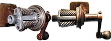
In the 11th century AD, epicyclic gearing was reinvented by Ibn Khalaf al-Muradi in Al-Andalus. His geared water clock employed a complex gear railroad train mechanism that included both segmental and epicyclic gearing.[6] [7]
Richard of Wallingford, an English abbot of St Albans monastery, subsequently described epicyclic gearing for an astronomical clock in the 14th century.[8] In 1588, Italian military engineer Agostino Ramelli invented the bookwheel, a vertically-revolving bookstand containing epicyclic gearing with two levels of planetary gears to maintain proper orientation of the books.[8] [9]
French mathematician and engineer Desargues designed and synthetic the first mill with epicycloidal teeth ca. 1650.[10]
Gear ratio of standard epicyclic gearing [edit]

In this case, the carrier (green) is held stationary while the sun gear (xanthous) is used as input. Assay assumes a common gear pattern modulus. The planet gears (blueish) turn in a ratio determined by the number of teeth in each gear. Here, the ratio is −24/16, or −3/2; each planet gear turns at three/2 the rate of the dominicus gear, in the contrary direction.
The gear ratio of an epicyclic gearing system is somewhat not-intuitive, particularly considering there are several ways in which an input rotation tin be converted into an output rotation. The iii basic components of the epicyclic gear are:
- Sun: The fundamental gear
- Carrier: Holds one or more peripheral Planet gears, all of the same size, meshed with the sun gear
- Ring or Annulus: An outer band with inward-facing teeth that mesh with the planet gear or gears
The overall gear ratio of a elementary planetary gearset can be calculated using the following two equations,[1] representing the lord's day-planet and planet-ring interactions respectively:

where
- is the athwart velocity of the Ring, Lord's day gear, Planet gears and planet Carrier respectively, and

- is the Number of teeth of the Ring, the Sun gear and each Planet gear respectively.

from which we can derive the following:


and

Considering .[11]

Alternatively, if the number of teeth on each gear meets the human relationship , this equation can be re-written as the following:


where

These relationships can exist used to clarify any epicyclic system, including those, such equally hybrid vehicle transmissions, where two of the components are used as inputs with the 3rd providing output relative to the ii inputs.[12]
In many epicyclic gearing systems, ane of these 3 basic components is held stationary; one of the ii remaining components is an input, providing power to the system, while the terminal component is an output, receiving power from the system. The ratio of input rotation to output rotation is dependent upon the number of teeth in each gear, and upon which component is held stationary.
In one organisation, the planetary carrier (dark-green) is held stationary, and the sun gear (xanthous) is used as input. In this instance, the planetary gears just rotate about their ain axes (i.e., spin) at a rate determined by the number of teeth in each gear. If the sun gear has Ns teeth, and each planet gear has Np teeth, so the ratio is equal to −Ns /Northp . For instance, if the dominicus gear has 24 teeth, and each planet has 16 teeth, then the ratio is −24/xvi, or −3/ii; this means that one clockwise plow of the dominicus gear produces 1.5 counterclockwise turns of each of the planet gear(s) almost its axis.
This rotation of the planet gears can in turn bulldoze the ring gear (non depicted in diagram), in a respective ratio. If the band gear has Northwardr teeth, then the ring volition rotate past Np /Northr turns for each plough of the planet gears. For instance, if the band gear has 64 teeth, and the planets xvi, one clockwise plow of a planet gear results in 16/64, or ane/4 clockwise turns of the ring gear. Extending this case from the ane to a higher place:
And then, with the planetary carrier locked, i turn of the sun gear results in turns of the ring gear.

The ring gear may also be held stock-still, with input provided to the planetary gear carrier; output rotation is and so produced from the sun gear. This configuration will produce an increase in gear ratio, equal to 1+Due northr /Ns .[ citation needed ]
If the ring gear is held stationary and the sun gear is used equally the input, the planet carrier will be the output. The gear ratio in this example will be one/(1 +Nr /Ndue south ) which can also be written as 1:(ane +Due northr /Northdue south ). This is the lowest gear ratio accessible with an epicyclic gear train. This type of gearing is sometimes used in tractors and structure equipment to provide loftier torque to the drive wheels.
In cycle hub gears, the sun is commonly stationary, existence keyed to the axle or even machined directly onto it. The planetary gear carrier is used as input. In this case the gear ratio is merely given past (Ns +Nr )/Nr . The number of teeth in the planet gear is irrelevant.
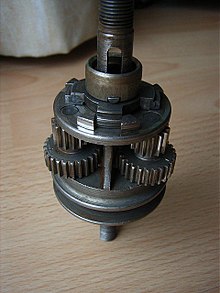
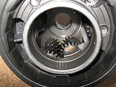
Compound planets of a Sturmey-Archer AM wheel hub (ring gear removed)
Accelerations of standard epicyclic gearing [edit]
From the in a higher place formulae, nosotros tin can as well derive the accelerations of the sun, band and carrier, which are:


Torque ratios of standard epicyclic gearing [edit]
In epicyclic gears, two speeds must be known, in guild to determine the third speed. Even so, in a steady state status, only 1 torque must be known, in club to determine the other ii torques. The equations which determine torque are:


where: — Torque of band (annulus), — Torque of lord's day, — Torque of carrier. For all three, these are the torques practical to the mechanism (input torques). Output torques have the reverse sign of input torques.


In the cases where gears are accelerating, or to account for friction, these equations must be modified.
Fixed carrier train ratio [edit]
A user-friendly arroyo to make up one's mind the diverse speed ratios available in a planetary gear train begins past considering the speed ratio of the gear railroad train when the carrier is held fixed. This is known equally the fixed carrier railroad train ratio.[two]
In the case of a simple planetary gear train formed by a carrier supporting a planet gear engaged with a sunday and ring gear, the stock-still carrier train ratio is computed as the speed ratio of the gear train formed past the sun, planet and ring gears on the fixed carrier. This is given by

In this calculation the planet gear is an idler gear.
The central formula of the planetary gear railroad train with a rotating carrier is obtained by recognizing that this formula remains truthful if the athwart velocities of the sun, planet and ring gears are computed relative to the carrier athwart velocity. This becomes,

This formula provides a simple manner to determine the speed ratios for the simple planetary gear railroad train under dissimilar atmospheric condition:
1. The carrier is held stock-still, ωc=0,

two. The band gear is held fixed, ωr=0,

3. The sun gear is held fixed, ωs=0,

Each of the speed ratios available to a simple planetary gear train can exist obtained by using band brakes to agree and release the carrier, dominicus or ring gears as needed. This provides the basic structure for an automatic transmission.
Spur gear differential [edit]
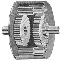
A spur gear differential constructed by engaging the planet gears of 2 co-centric epicyclic gear trains. The casing is the carrier for this planetary gear train.
A spur gear differential is constructed from 2 identical coaxial epicyclic gear trains assembled with a single carrier such that their planet gears are engaged. This forms a planetary gear train with a fixed carrier train ratio R = −ane.
In this instance, the fundamental formula for the planetary gear train yields,

or

Thus, the angular velocity of the carrier of a spur gear differential is the average of the athwart velocities of the lord's day and ring gears.
In discussing the spur gear differential, the use of the term ring gear is a user-friendly way to distinguish the sunday gears of the ii epicyclic gear trains. Ring gears are usually fixed in virtually applications as this arrangement volition have a good reduction capacity. The second sun gear serves the same purpose every bit the ring gear of a simple planetary gear train merely clearly does non take the internal gear mate that is typical of a ring gear.[1]
Gear ratio of reversed epicyclic gearing [edit]
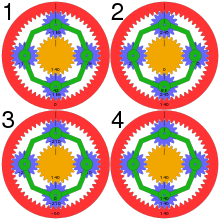
CSS animations of epicyclic gearing with 56-tooth ring gear locked (1), 24-molar sun gear locked (2), carrier with xvi-tooth planetary gears locked (three) and direct drive (4) – numbers denote relative angular speed
Some epicyclic gear trains utilise 2 planetary gears which mesh with each other. One of these planets meshes with the sun gear, the other planet meshes with the ring gear. This results in different ratios beingness generated by the planetary. The fundamental equation becomes:

where

which results in:
- when the carrier is locked,

- when the sun is locked,

- when the ring gear is locked.

Compound planetary gears [edit]
"Chemical compound planetary gear" is a general concept and it refers to any planetary gears involving one or more of the following three types of structures: meshed-planet (there are at least ii or more than planets in mesh with each other in each planet train), stepped-planet (in that location exists a shaft connection between ii planets in each planet train), and multi-stage structures (the system contains two or more planet sets).
Some designs apply "stepped-planet" which have two differently-sized gears on either end of a common shaft. The pocket-sized finish engages the sun, while the large end engages the ring gear. This may exist necessary to achieve smaller pace changes in gear ratio when the overall package size is express. Compound planets have "timing marks" (or "relative gear mesh phase" in technical term). The associates conditions of compound planetary gears are more restrictive than elementary planetary gears,[13] and they must be assembled in the correct initial orientation relative to each other, or their teeth will not simultaneously engage the sun and ring gear at opposite ends of the planet, leading to very rough running and short life. In 2015, a traction based variant of the "stepped-planet" design was developed at the Delft Academy of Technology, which relies on compression of the stepped planet elements to achieve torque transmission. The use of traction elements eliminates the demand to "timing marks" as well as the restrictive associates conditions as typically establish. Compound planetary gears can easily achieve larger transmission ratio with equal or smaller volume. For example, compound planets with teeth in a 2:one ratio with a 50T ring gear would give the same effect as a 100T ring gear, but with half the actual diameter.
More than planet and sun gear units can be placed in series in the aforementioned housing (where the output shaft of the offset phase becomes the input shaft of the next phase) providing a larger (or smaller) gear ratio. This is the mode most automatic transmissions work. In some cases multiple stages may even share the same ring gear which can be extended down the length of the transmission, or even be a structural office of the casing of smaller gearboxes.
During World War II, a special variation of epicyclic gearing was adult for portable radar gear, where a very high reduction ratio in a small packet was needed. This had two outer ring gears, each one-half the thickness of the other gears. One of these two ring gears was held fixed and had one tooth fewer than did the other. Therefore, several turns of the "sun" gear made the "planet" gears complete a unmarried revolution, which in turn made the rotating band gear rotate past a single tooth like a cycloidal drive.[ citation needed ]
Benefits [edit]
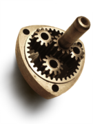
The mechanism of a pencil sharpener with stationary ring gear and rotating planet carrier as input. Planet gears are extended into cylindrical cutters, rotating around the pencil that is placed on the sun axis. The axes of planetary gears join at the pencil sharpening angle.
Planetary gear trains provide high power density in comparison to standard parallel axis gear trains. They provide a reduction in volume, multiple kinematic combinations, purely torsional reactions, and coaxial shafting. Disadvantages include high begetting loads, constant lubrication requirements, inaccessibility, and blueprint complexity.[14] [15]
The efficiency loss in a planetary gear train is typically about iii% per stage. This blazon of efficiency ensures that a loftier proportion (well-nigh 97%) of the energy beingness input is transmitted through the gearbox, rather than being wasted on mechanical losses within the gearbox.
The load in a planetary gear railroad train is shared among multiple planets; therefore, torque adequacy is greatly increased. The more planets in the system, the greater the load ability and the higher the torque density.
The planetary gear train also provides stability due to an even distribution of mass and increased rotational stiffness. Torque practical radially onto the gears of a planetary gear railroad train is transferred radially by the gear, without lateral pressure level on the gear teeth.
In a typical application, the drive power connects to the sun gear. The sun gear then drives the planetary gears assembled with the external gear ring to operate. The whole set up of planetary gear arrangement revolves on its ain axis and forth the external gear band where the output shaft continued to the planetary carrier achieves the goal of speed reduction. A higher reduction ratio tin be achieved by doubling the multiple staged gears and planetary gears which can operate inside the same band gear.
The method of move of a planetary gear structure is different from traditional parallel gears. Traditional gears rely on a pocket-size number of contact points between ii gears to transfer the driving force. In this example, all the loading is concentrated on a few contacting surfaces, making the gears wearable speedily and sometimes cleft. Simply the planetary speed reducer has multiple gear contacting surfaces with a larger area that can distribute the loading evenly around the central axis. Multiple gear surfaces share the load, including any instantaneous bear on loading, evenly, which brand them more resistant to harm from higher torque. The housing and bearing parts are also less probable to be damaged from loftier loading every bit only the planet carrier bearings feel significant lateral force from the transmission of torque, radial forces oppose each other and are balanced, and centric forces only arise when using helical gears.
3D printing [edit]
Blitheness of a printable gear set. Legend: driving shaft (green), ring gear (nighttime gray), planet gears (blue), sun gear/driven shaft and carrier (red).
Planetary gears have become popular in 3D press for a few unlike reasons. Planetary gear boxes tin can provide a big gear ratio in a pocket-size, light-weight parcel. Some people install such gearboxes to get more than accurate 3D prints by gearing-down the movement of their stepper motors.
A geared-down motor must plow further and faster in order to produce the same output movement in the 3D printer which is advantageous if it is non outweighed by the slower movement speed. If the stepper motor has to turn farther then it besides has to accept more steps to move the printer a given distance; therefore, the geared-downward stepper motor has a smaller minimum step-size than the aforementioned stepper motor without a gearbox. While there are many involved factors, planetary gearboxes may aid produce very high quality 3D prints.
Ane popular use of 3D printed planetary gear systems is every bit toys for children.[ citation needed ] Since herringbone gears are easy to 3D print, it has become very popular to 3D impress a moving herringbone planetary gear system for pedagogy children how gears work. An reward of herringbone gears is that they don't autumn out of the band and don't need a mounting plate, allowing the moving parts to be clearly seen.
Gallery [edit]
-

Split ring, compound planet, epicyclic gears of a car rear-view mirror positioner. This has a ratio from input sunday gear to output black ring gear of −5/352.
-
-
I of three sets of three gears inside the planet carrier of a Ford FMX Ravigneaux transmission
Come across also [edit]
- Hypocycloidal gearing
- Antikythera machinery – ancient mechanical astronomical computer
- Continuously variable transmission (CVT)
- Cycloidal bulldoze
- Epicycloid
- Ford Model T – had a ii speed planetary transmission.
- Gearbox
- Harmonic bulldoze
- Hub gear, for bicycles, etc.
- NuVinci Continuously Variable Transmission
- Ravigneaux planetary gearset
- Rohloff Speedhub – xiv-ratio wheel hub gearbox
- Simpson planetary gearset
- Sturmey Archer – First major manufacturer of bicycle hubs using planetary gears
References [edit]
- ^ a b c J. J. Uicker, G. R. Pennock and J. E. Shigley, 2003, Theory of Machines and Mechanisms, Oxford University Press, New York.
- ^ a b B. Paul, 1979, Kinematics and Dynamics of Planar Mechanism, Prentice Hall.
- ^ Hillier, V.A.W. (2001). "Planetary gearing and unidirectional clutches". Fundamentals of Motor Vehicle Technology (4th ed.). Cheltenham, Britain: Nelson Thornes. p. 244. ISBN0-74-870531-7.
- ^ Harrison, H.; Nettleton, T. (1994). Principles of Engineering Mechanics (2nd ed.). Oxford, UK: Butterworth-Heinemann. p. 58. ISBN0-34-056831-3.
- ^ Wright, M. T. (2007). "The Antikythera Mechanism reconsidered" (PDF). Interdisciplinary Scientific discipline Reviews. 32 (i): 27–43. doi:x.1179/030801807X163670. Retrieved 20 May 2014.
- ^ Hassan, Ahmad Y., Transfer Of Islamic Technology To The West, Part 2: Transmission Of Islamic Engineering, History of Science and Engineering in Islam
- ^ Donald Routledge Hill (1996). A history of technology in classical and medieval times. Routledge. pp. 203, 223, 242. ISBN0-415-15291-7.
- ^ a b JJ Coy, DP Townsend, EV Zaretsky, "Gearing", NASA Reference Publication 1152, AVSCOM Technical Report 84-C-xv, 1985
- ^ Republic of chad Randl, "Revolving compages: a history of buildings that rotate, swivel, and pin", p19
- ^ Musson; Robinson (1969). Science and Technology in the Industrial Revolution . University of Toronto Printing. p. 69.
- ^ "How to derive and calculate epicyclic gear ratio equations in planetary gear systems".
- ^ John 1000. Miller (May 2006). "Hybrid electric vehicle propulsion system architectures of the e-CVT type". IEEE Transactions on Power Electronics. 21 (three): 756–767. Bibcode:2006ITPE...21..756M. doi:10.1109/TPEL.2006.872372.
- ^ P. A. Simionescu (1998-09-01). "A Unified Approach to the Assembly Condition of Epicyclic Gears". Journal of Mechanical Design. 120 (iii): 448–453. doi:10.1115/one.2829172.
- ^ Lynwander, P., 1983, Gear Drive Systems: Blueprint and Application. Marcel Dekker, New York
- ^ Smith, J. D., 1983, Gears and Their Vibration: A Basic Approach to Understanding Gear Racket. Marcel Dekker, New York and MacMillan, London
External links [edit]
- Kinematic Models for Design Digital Library (KMODDL), movies and photos of hundreds of working mechanical-systems models at Cornell.
- "Epicyclic gearing animation in SVG"
- "Animation of Epicyclic gearing"
- The "Power Split Device"
- The "Interactive Planetary Gearset tutorial"
- Prius Gearbox
- Planetary Gearbox
- Ph.D. Dissertation on Chemical compound Planetary Gears
- Brusque Cuts for Analyzing Planetary Gearing
- Vectorial animation: annulus, planets and sun gear.
DOWNLOAD HERE
The Epicyclic Gear Train Is Driven by the Rotating Link De UPDATED
Posted by: dianethilethe.blogspot.com